CHAPTER 5
THE SCREW
CHAPTER LEARNING OBJECTIVES
Upon completion of this chapter, you should be able to do the following:
- State the uses of the screw.
- Explain the use of the jack.
- Discuss the use of the micrometer
The screw is a simple machine that has many uses. The vise on a workbench makes use of the mechanical advantage (M.A.) of the screw. You get the same advantage using glued screw clamps to hold pieces of furniture together, a jack to lift an automobile, or a food processor to grind meat.
A screw is a modification of the inclined plane. Cut a sheet of paper in the shape of a right triangle and you have an inclined plane. Wind this paper around a pencil,
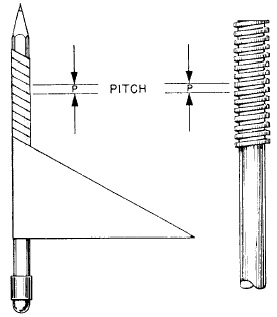
Figure 5-1.—A screw is an inclined plane in spiral form.
as in figure 5-1, and you can see that the screw is actually an inclined plane wrapped around a cylinder. As you turn the pencil, the paper is wound up so that its hypotenuse forms a spiral thread. The pitch of the screw and paper is the distance between identical points on the same threads measured along the length of the screw.
THE JACK
To understand how the screw works, look at figure 5-2. Here you see the type of jack screw used to raise a house or apiece of heavy machinery. Notice that the jack has a lever handle; the length of the handle is equal to r.
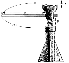
Figure 5-2.-A jack screw.
If you pull the lever handle around one turn, its outer end has described a circle. The circumference of this circle is equal to 2p. (Remember that p equals 3.14, or 22/7). That is the distance you must apply the effort of the lever arm.
At the same time, the screw has made one revolution, raising its height to equal its pitch (y). You might say that one full thread has come up out of the base. At any rate, the load has risen a distance p.
Remember that the theoretical mechanical advantage (T.M.A.) is equal to the distance through which you apply the effort or pull, divided by the distance and resistance the load is moved. Assuming a 2-foot, or 24-inch, length for the lever arm and a 1/4-inch pitch for the thread, you can find the theoretical mechanical advantage by the formula
T.M.A. = ![]()
in that
r = length of handle = 24 inches
p = pitch, or distance between corresponding points on successive threads = 1/4 inch.
Substituting,
![]()
A 50-pound pull on the handle would result in a theoretical lift of 50 x 602 or about 30,000 pounds—15 tons for 50 pounds.
However, jacks have considerable friction loss. The threads are cut so that the force used to overcome friction is greater than the force used to do useful work. If the threads were not cut this way and no friction were present, the weight of the load would cause the jack to spin right back down to the bottom as soon as you released the handle.
THE MICROMETER
In using the jack you exerted your effort through a distance of 2pr, or 150 inches, to raise the screw 1/4 inch. It takes a lot of circular motion to get a small amount of straight line motion from the head of the jack. You will use this point to your advantage in the micrometer; it’s a useful device for making accurate small measurements—measurements of a few thousandths of an inch.
In figure 5-3, you see a cutaway view of a micrometer. The thimble turns freely on the sleeve,
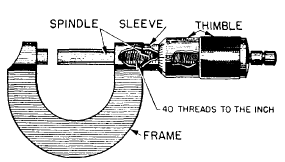
Figure 5-3.-A micrometer.
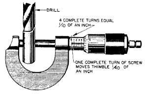
Figure 5-4.—Taking turns.
rigidly attached to the micrometer frame. The spindle attaches to the thimble and is fitted with screw threads that move the spindle and thimble to the right or left in the sleeve when you rotate the thimble. These screw threads are cut 40 threads to the inch. Hence, one turn of the thimble moves the spindle and thimble 1/40 of inch. This represents one of the smallest divisions on the micrometer. Four of these small divisions make 4/40 of an inch, or 1/10 inch. Thus, the distance from 0 to 1 or 1 to 2 on the sleeve represents 1/10, or 0.1, inch.
To allow even finer measurements, the thimble is divided into 25 equal parts. It is laid out by graduation marks around its rim, as shown in figure 5-4. If you turn the thimble through 25 of these equal parts, you have made one complete revolution of the screw. This represents a lengthwise movement of 1/40 of an inch. If you turn the thimble one of these units on its scale, you have moved the spindle a distance of 1/25 of 1/40 inch, or 1/1000 of an inch—0.001 inch.
The micrometer in figure 5-4 reads 0.503 inch, that is the true diameter of the half-inch drill-bit shank measured. This tells you that the diameter of this bit is 0.003 inch greater than its nominal diameter of 1/2 inch—0.5000 inch.

Figure 5-5.—A turnbuckle.
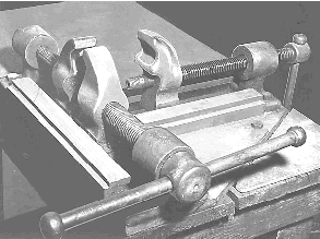
Figure 5-6.-A rigger’s vice.
Because you can make accurate measurements with this instrument, it is vital in every machine shop.
APPLICATIONS AFLOAT AND ASHORE
It’s a tough job to pull a rope or cable tight enough to get all the slack out of it. However, you can do it by using a turnbuckle. The turnbuckle (fig, 5-5) is an application of the screw. If you turn it in one direction, it takes up the slack in a cable. Turning it the other way allows slack in the cable. Notice that one bolt of the turnbuckle has left-hand threads and the other bolt has right-hand threads. Thus, when you turn the turnbuckle to tighten the line, both bolts tighten up. If both bolts were right-hand thread-standard thread-one would tighten while the other one loosened an equal amount. That would result in no change in cable slack. Most turnbuckles have the screw threads cut to provide a large amount of frictional resistance to keep the turnbuckle from unwinding under load. In some cases, the turnbuckle has a locknut on each of the screws to prevent slipping. You’ll find turnbuckles used in a hundred different ways afloat and ashore.
Ever wrestled with a length of wire rope? Obstinate and unwieldy, wasn’t it? Riggers have dreamed up tools to help subdue wire rope. One of these tools-the rigger’s vise-is shown in figure 5-6. This rigger’s vise uses the mechanical advantage of the screw to hold the wire rope in place. The crew splices a thimble-a reinforced loop—onto the end of the cable. Rotating the handle causes the jaw on
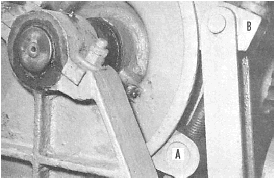
Figure 5-7.—A friction brake.
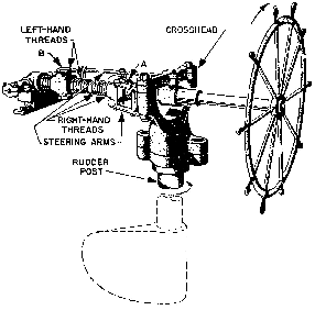
Figure 5-8.—The screw gives a tremendous mechanical advantage.
that screw to move in or out along its grooves. This machine is a modification of the vise on a workbench. Notice the right-hand and left-hand screws on the left-hand clamp.
Figure 5-7 shows you another use of the screw. Suppose you want to stop a winch with its load suspended in mid-air. To do this, you need a brake. The brakes on most anchor or cargo winches consist of a metal band that encircles the brake drum. The two ends of the band fasten to nuts connected by a screw attached to a handwheel. As you turn the handwheel, the screw pulls the lower end of the band (A) up toward its upper end (B). The huge mechanical advantage of the screw puts the squeeze on the drum, and all rotation of the drum stops.
One type of steering gear used on many small ships and as a spare steering system on some larger ships is the screw gear. Figure 5-8 shows you that the
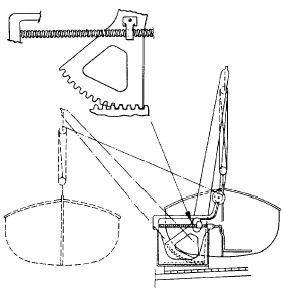
Figure 5-9.—The quadrant davit.
wheel turns a long threaded shaft. Half the threads— those nearer the wheel end of this shaft-are right-hand threads. The other half of the threads-those farther from the wheel—are left-hand threads. Nut A has a right-hand thread, and nut B has a left-hand thread. Notice that two steering arms connect the crosshead to the nuts; the crosshead turns the rudder. If you stand in front of the wheel and turn it in a clockwise direction— to your right—arm A moves forward and arm B moves backward. That turns the rudder counterclockwise, so the ship swings in the direction you turn the wheel. This steering mechanism has a great mechanical advantage.
Figure 5-9 shows you another practical use of the screw. The quadrant davit makes it possible for two men to put a large lifeboat over the side with little effort. The operating handle attaches to a threaded screw that passes through a traveling nut. Cranking the operating handle in a counterclockwise direction (as you face outboard), the nut travels outward along the screw. The traveling nut fastens to the davit arm by a swivel. The davit arm and the boat swing outboard as a result of the outward movement of the screw. The thread on that screw is the self-locking type; if you let go of the handle, the nut remains locked in position.
SUMMARY
You have learned the following basic information about the screw from this chapter; now notice the different ways the Navy uses this simple machine:
The screw is a modification of the inclined plane— modified to give you a high mechanical advantage.
The theoretical mechanical advantage of the screw can be found by the formula
![]()
As in all machines, the actual mechanical advantage equals the resistance divided by the effort.
In many applications of the screw, you make use of the large amount of friction that is commonly present in this simple machine.
By using the screw, you reduce large amounts of circular motion to very small amounts of straight-line motion.


No comments:
Post a Comment